


Serial ATA Disk Drive Basics
Installing a serial ATA drive on your system should be simple and almost transparent. Most of the new motherboards which incorporate serial ATA connectors do not provide options for adjustment in the BIOS, so you should not have to change anything in the BIOS if you are adding a drive.
If you are replacing your boot drive, you may have to change the "boot order" in the BIOS to boot from the serial ATA controller (sometimes represented in the boot order as the drive model number and sometimes as SCSI). See Document ID: 184911 for information on loading the SATA drivers and installing the SATA drive in Windows . The SATA drivers for Windows 2000 and Windows XP are loaded during the install of the operating system by hitting the F6 button when prompted. The system continues to load and then will stop and ask for the mass storage device driver. At this time put your disc with the driver in the CD-ROM / DVD drive and load the driver.
When performing a new installation from DVD of Windows 10/8.1/8/7 or Vista, a box will prompt “Where do you want to install Windows?”. If the SATA hard drive is not showing then click the Load Driver option. We recommend going to the serial ATA controller manufacturer's website for the latest drivers
If you install your serial ATA drive and it is not seen by the operating system then confirm you have loaded the latest driver for your host adapter. If the drive is plugged into the motherboard then the drivers are provided by the motherboard manufacturer. If the drive is plugged into a PCI card then check with the manufacturer of the PCI card. You will, of course, need to partition and format the drive, but this will also be done outside the BIOS environment.
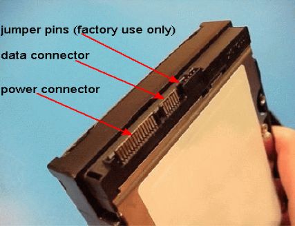
The image below shows typical connector examples for a serial ATA drive. The largest connector on the edge of the drive is the power connector. The middle, smaller connector is the data connector for the serial ATA data cable, and the jumper pins on the right are for factory use only. An adapter for the power connector is provided in your disk drive kit, as well as a data cable. There are no adjustments to be made to the jumper block. Both connectors on the drive are "keyed", which means the cables will only slide on one way.
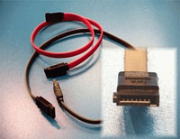
The images below show some typical serial ATA data cables with which you may be working. The image on the left shows data cables which were industry-standard when serial ATA first appeared. The connector plugs are identical on either end and keyed, so they will only plug into the motherboard, controller, or drive one way.
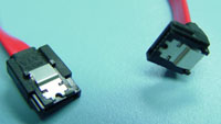
The image on the right shows new data cables with the latching fastener, which allows the cable to latch to the drive connector and prevent the cable from coming off. The plugs may not be identical on both ends (some may have a ninety-degree bend for ease-of-use), but they will fit on all serial ATA drive connections, motherboards and PCI cards. These latching connectors were designed to minimize shipping and handling mishaps which cause the connector to come off.
In either case, the connector plugs are identical on either end and keyed, so they will only plug into the motherboard, controller or drive one way. If you have a large computer case and/or your serial ATA drive must be located very far from your motherboard or controller, a longer data cable may be required.
Disclaimer: This document is provided as is without any warranty of any kind, either expressed or implied. In no event will Seagate be liable to you for any damages, including any loss of profit or savings, arising out of the use or inability to use the information contained in this Document. Seagate Corporation makes no representations or warranties with respect to the contents hereof and specifically disclaims any implied warranties of merchantability or fitness for any particular purpose.
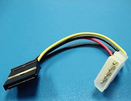
The image below is the power adaptor cable which comes with your retail kit. The connectors are keyed and cannot easily be connected in error. The white power plug is industry-standard and may be connected to any power cable within reach inside your computer. The black/brown plug connects to your disk drive. This connector is double-slotted and will only go onto your disk drive in one way.
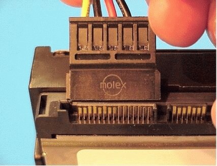
The image below is a close up of the power adaptor cable which comes with your retail kit, and the disk drive power connector.
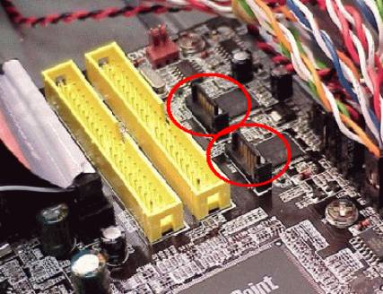
The image below shows two typical serial ATA data connectors (circled) on a motherboard. On another motherboard, the location may be slightly different, but the connector itself will look the same.
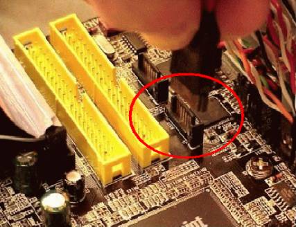
The image below shows a serial ATA data cable about to be installed onto a serial ATA connector on a motherboard.
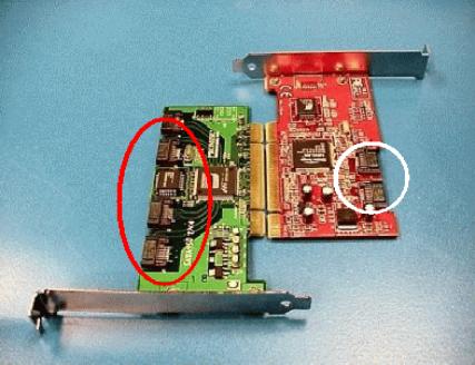
The image below shows two typical serial ATA controller cards. These cards install into a standard PCI slot on the motherboard, and may contain one to four or more connectors for serial ATA data cables. You may plug a data cable into any of the connectors. There is no particular order needed. Serial ATA controller cards will come with driver files, which will need to be used when Windows asks for them.
Although Seagate and Maxtor serial ATA disk drives do not need drivers to function, it is probable your serial ATA controller will. If you do not have drivers available, please consult the website of your controller manufacturer to see if there are any drivers available. There is also good information on this SATA troubleshooting page if you are having problems installing your serial ATA drive.
The image below shows a serial ATA data cable installed onto a serial ATA connector on a PCI card.
